BATTERY BOX INSTALL
PLUS FLOAT HEIGHT ADJUSTMENT
(Large and Small), Flat Blade Screwdrivers (Large, Small and
Extra Small), 6mm-12mm End Wrenches, Spray Lube, Tin
Snips, Drill and Bits, Marker and Tape, Pliers, and Some
Other Stuff I Forgot About...
work than I thought it would be. I took over 130 pictures, and thinned it down to what you
see here. All my testing so far indicates that this was a very worthwhile mod, though. Special
thanks goes to Chris Kelley at California Cycelworks. Thanks for all the parts and trouble!
There has been tremendous interest in this setup, and I failed to mention earlier that I
ordered the filters (K&N RU-1750's) through Chris at California Cycleworks, they ran about
$40 each. I also ordered the Factory Pro jet kit and new needle jets through Chris. I have
also seen the filters in the Chaparral Racing catalog for a bit less, but I prefer Chris' friendly
and personal service over theirs.
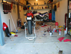
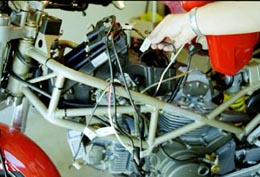
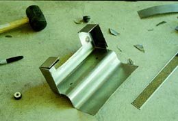
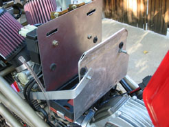
work it took. Making a battery box is a long process, but as you can see from
the pics it is well worth it. The box took 80% of the time involved (I made 3
different ones!), but I didn't want to cut my original piece, and I wanted to
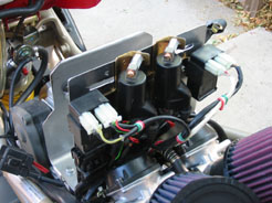
flip the coils around and mount them on the back of my new box. It looks
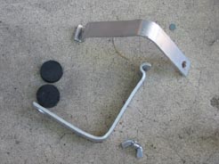
like it's just a piece of flat metal bent in two spots, but it's more than that.
The front top edge is rolled, and notched to clear the battery cables and the
hold-downs are aluminum strap bent to perfection :)
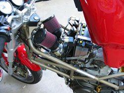

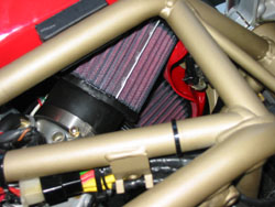
The filters just look wicked mean,
they sound awesome, the carbs are
SO much easier to service now, it
runs cooler without the box blocking
everything up, and I saved some
weight on top of it all.
<<<CLICK FOR A FULLSIZE PIC
Changed the float level from the stock 9mm and 12mm (yes, they were uneven) to the Factory Pro recommended 14mm.
Main jets are 142.5 (largest supplied, 132.5 is stock), pilot jets are 42.5 (40 is stock, 45 is also optional).
Needle position changed from # 4 (!) to #2, and the optional lighter springs were used.
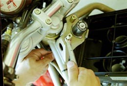
Throttle cable mounts were fixed, as they were previously tightened on crooked.
K&N RU-1750 pod filters installed.
Overall power and grunt seems maybe slightly better, but the way the power is delivered is vastly improved. It is so much
smoother, crisper, and stable. No more surging, bucking, spitting, stumbling, abrupt throttle response, etc.
Accelerating from a stop, it no longer surges when it recovers from the clutch engaging. In other words, I used to get a
stumble after I got going from a stop, but now it is very smooth all the way. Parking lot cruising is much smoother, no
lurching. It also pulls a lot stronger way down low.
It now pulls strong in low gear at low RPM and doesn't bog as much. Uphill in 2nd gear at 25MPH is smooth, and no
downshift is necessary.
Cruising at 25MPH in 2nd, 3,500 RPM, I whack the throttle open and it goes, fast I might add, without a hesitation or
pause as there used to be.
Power shifting at WOT stumbles depending on clutch technique. I haven't got a lot of full power runs in because it only
requires two gears to get to a good clip, but I bet I'll need to reduce the main jet size. Sometimes I get a super clean run
all the way to 100MPH in three gears, other times it'll fall flat if I shift to fourth. I'll give it some more testing before I
mess with anything.
Take-offs from stoplights and low RPM cruising in parking lots is greatly improved. Before it was very hard to keep a
slow, steady throttle, it was ALWAYS jerky. Now it is smoother.
Fuel economy increased from 33 MPG to almost 48MPG! Plus, I can now use 87 octane. Previously I had to use 92 or else
it would run really rough.
just plain blew. This is the best one by far. It's a way thicker gauge, is
very sturdy, and it was fairly simple to make. I was worried that it would
retain heat compared to the plastic, but I've reached in there when it's
running and it's only warm to the touch. The same goes for the filters- I
was going to make a heat shield, but at idle in heavy traffic in 95 degree
weather the air by the filters wasn't hot at all. The wood piece under the
battery has since been replaced with rubber sheet.
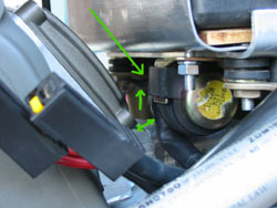
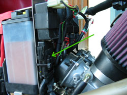
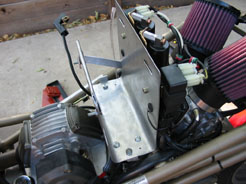
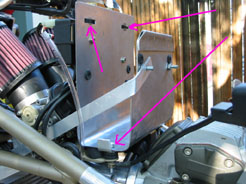
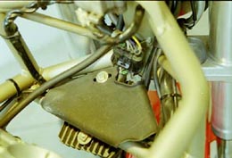
moved up and away from the head
further- it previously rested right on
the head. It also shows the re-used
mounting rubbers with metal inserts
(between the box and frame tabs).
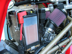
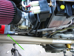
to the tab for the airbox mounting as shown by the arrow, bent it around
the back of the new battery box and mounted it there. It really stiffens the
whole unit up. The base is mounted using the original holes and some
rubber stoppers for cushioning.
the battery box, and the wires were
zip tied neatly out of the way.
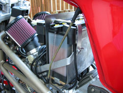
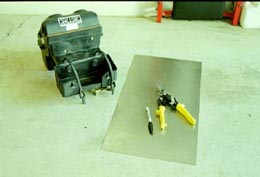
tray setup I concoted. I couldn't find
a large enough sheet in town, so I had
to cut up a smaller piece. When I
find a bigger one I will replace it, but
this works fine for now.
from the outside bottom right to the
inside center. You can also see the
new drain tubes for the float bowls
and the wacky green/white/red zip tie
job!
____________________________________________________________________________________________________
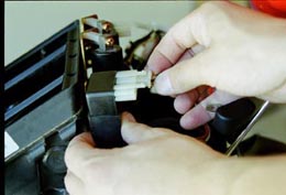
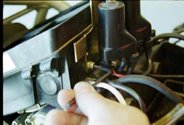
to the ignition modules, then slide those off of the mounting bracket. Make
sure you note which module is connected to which set of wires.
bracket from the airbox.
one goes to the horizontal and which one to the vertical. In my setup, I
mounted the coils to the back of the battery box, but had to switch the ignition
modules to the other sides so that the wires were long enough, and that gets
confusing.
battery box with an allen and wrench.
battery box to the carbs.
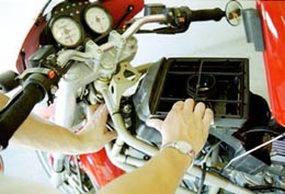
won't come out- it hits on the ignition switch. One time, I took out every
screw from the top of the airbox and took the top part off, but that was a joke!
It took a good hour to put it back together once it was back in. The next
time I just removed the ignition switch.
Then once it's off, you can hold the long nuts on top while unscrewing the
bolts from the bottom side with an allen.
it came off- first mount it to the frame, then install the
cover back on.
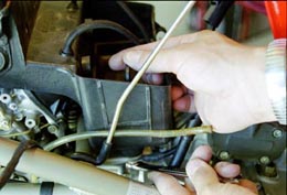
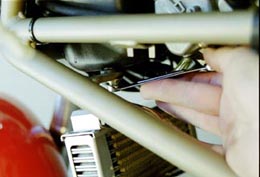
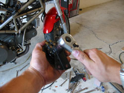
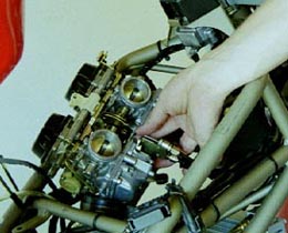
clamp from the intake runners to the carbs, and pop them loose. Then
when you can maneuver them up, slide the choke over and gently
remove the cable end from its hole.
bracket and free the cable from the carb.
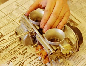
this point, you should be able to turn the carbs upside down. Put the float
bowl drain hoses into a container because when it is flipped the gas will gush
out.
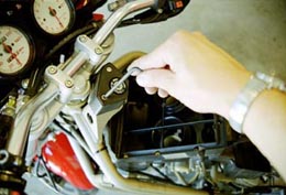
throttle cables from their holes. Be sure to label
which cable goes to which position
adjusters from their mounts using
your wrench. Once loose they will
slide right off.
new battery box. The first one was
shaped kind of like the old box,
where the coils would mount on a
kind of shelf. That didn't look
very good, so I made a second one
that worked pretty well but was too
big. The third one was a much
heavier gauge steel, and fit much
better. I had to use an air grinder
to cut it because it was too thick
for shears.
sheet in an 8x24" dimension, so very little
cutting was required. You can either cut
down the front wall so it is 6", or bend it over
like I did. You'll need to cut an indentation
into each side for the battery straps to clear.
You'll need two long (over 2") M5 screws to
thread into the frame tabs, two M5 nuts for
the coil bracket bolts, two nuts and bolts for
the starter solenoid mounting (standard or
metric, doesn't matter), a nut and bolt for
the stabilizer rod mounting to the frame
(again, standard or metric), 1/8" aluminum
strap (probably two 36" pieces), and two 1/4"
flat head machine screws and 1/4" wingnuts
for the hold down straps. You'll also need
some rubber for the bottom of the tray to
prevent vibration. There's no sense in
showing the step by step of making it,
because it is really simple, and each bike has
the mounting tabs, solenoids, etc. in different
places. Each bike's box will need to be
custom, sorry!
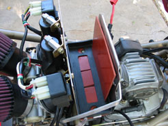
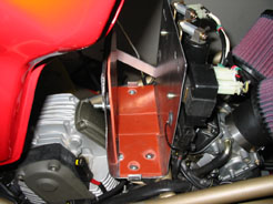
original box mounting tabs. The red stuff is rubber material to absorb vibration, the black rubber is the OE tray. The
third pic shows the tray without the rubber pads.
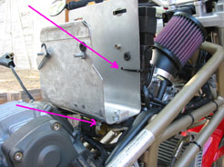
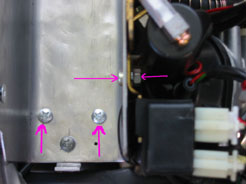
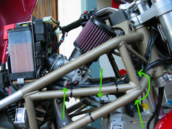
needed to secure the bolts (it originally had nuts mounted in the plastic airbox). The two arrows pointing to screws are the
starter solenoid mounting screws. The third pic shows an arrow pointing to the starter solenoiud, and also to the hole
drilled in the box to accomodate the zip tie for the main fuse. Of course, the minor details vary from year to year, so
yours will need to be custom to fit your needs.
out from underneath and bent up on each side to stop the battery from sliding side to side. It is mounted directly between
the tray and the mounting rubbers (which are the little round rubber pieces with metal inserts that you need to scavenge
from the original airbox). A new, longer screw goes from the top of the new battery tray, through the rubbers, and
threads into the original mounting tabs on the frame.
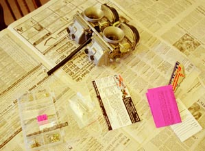
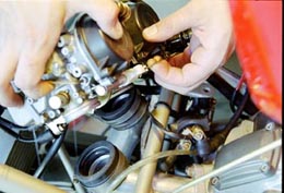
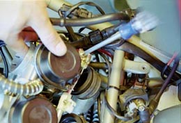
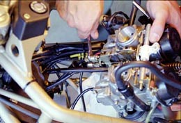
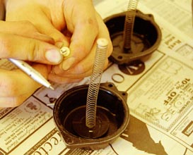
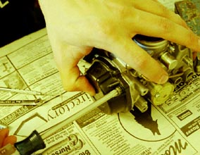
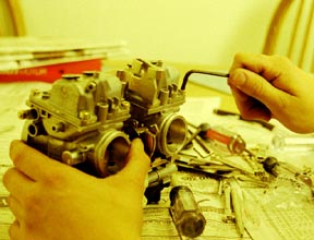
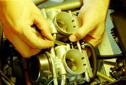
carbs. They were awfully clean, so I just just used a little choke cleaner
to get them spruced up (outside the house of course). Then I laid out all
the parts to get an idea of what I was doing. Then, most importantly, I
read the instructions to figure out what size jets and what needle
position I should use.
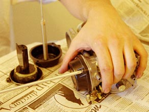
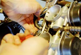
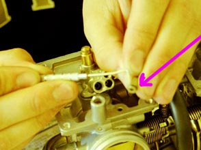
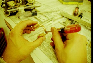
the needle / diaphragm slide assembly.
o-ring, it's not secured to anything
and just falls out (don't forget to put
it back before installing the covers).
supplied springs, which provide a better part
throttle "snap" as they call it.
needle. It's kind of like a baseball bat with donuts (mmm.... donuts....)- the
washer has to slide off towards the tapered end. Don't place the needle
against something hard and push down- it will surely ruin the tip and you
may need to switch back to them later, you never know.
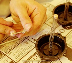
chose #2 for a slightly leaner part throttle mixture. #2 means the second
position going from the large end, not the needle end. #2, therefore, places the
needle further into the bore of the needle jet (needle valve, emulsion tube,
whatever), meaning less fuel flows by under part throttle cruising. Slide the
nylon washer onto the new needles and then put on the stock steel washer.
carb's bore. At the same time, make sure the needle goes into the needle jet
easily and doesn't get crooked and bound up. It's probably a good idea to
replace the needle jets before doing this or at the same time (read down
below on how to do that). Factory recommends replacing them every 5,000
miles on Mikunis because they wear fast and get "ovaled" by the needle.
This allows more fuel in at part throttle and causes a rich mixture. Mine
probably could have been reused, but I didn't know that without tearing the
carbs down, so I just ordered new ones.
over the protrusion in the cover and into the bore of
the diaphragm, then button it up.
you're done on that end. Be sure not to overtighten them,
they only need to be snug.
screws off without damaging them, which is a good reason the
Factory Pro kit came with new screws.
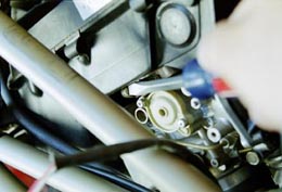
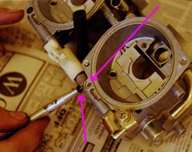
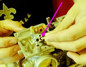
holding the tab that holds the main jet in.
tight fit, so be careful not to damage the o-ring when pulling it out.
o-ring from the main jet and place it on the new jet. Be
careful! It's small and could rip easily.
the supplied 142.5 because my exhaust is partially cored and I'm
using the pod filters. I'm still gathering info, but it's very possible
that I should have used a smaller main.
using. It's weird because 40 is stock- I don't know where the 42.5 came
from. 45 came with the kit as an option, but I'm shooting more for
economy and smooth running than power. It goes in and out with a
screwdriver (a smaller size, a little bigger than a jeweler's screwdriver).
When screwing it back in be GENTLE. You don't want to crack it.
have to hold it in place while tightening
the screw so that it doesn't move to the
side.
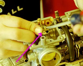
them at 2.75 turns out as recommended.
the screw cap with a 6mm wrench.
jet holder assembly- it slides off easily.
in the same way; there is a slot that has to line up in the bore of the carb
and on the holder. Once they're back in, place the cover back on and
screw on the cap GENTLY. Brass cracks easily. Just make it snug.
delivery as the jets. It's also next to impossible to do it with the carbs on the bike, so you might as well plan on taking
them off.
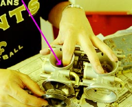
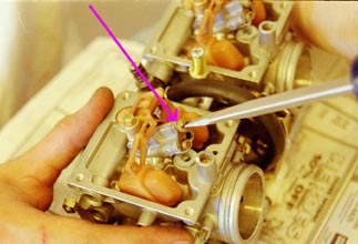
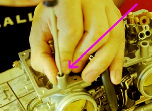
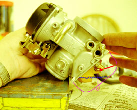
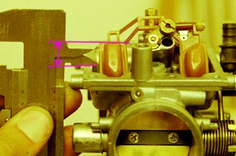
The carb on the left has a
drawing of where the float bowl
normally is (pink line). The
blue line is the fuel level inside
the bowl. The float is mounted
on a pivot point, and can move
up and down with the fuel level
(hence the name float). It's the
float's job to keep an adequate
amount of fuel in the bowls for
sudden increases in power (you
don't want the bike to die
because of lack of fuel),
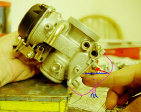
when the engine doesn't demand fuel), it pushes the float up, which in turn pushes up the metering deal thinger (I want
to say rod, but Ducati doesn't call it that) into its bore to plug the fuel delivery passage and cut off the fuel flow. If the
level rises too much, the fuel can flow out of the drain tubes located inside the bowls. If the fuel level lowers (such as
under acceleration) the float sinks, pulling the metering dealer out and letting fuel flow into the bowls.
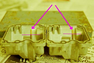
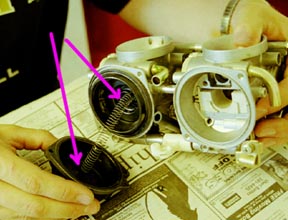
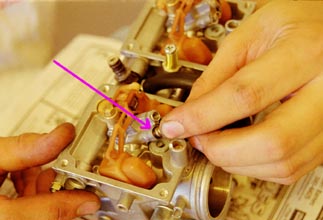
correctly from the factory, and they're usually too rich. This
illustrates how they were set too rich, and also unevenly!
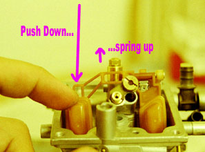
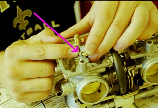
metering dealy things have springs on the very ends. As you push
down, they will compress, but should spring back up. You want to
check the height with them sprung up.
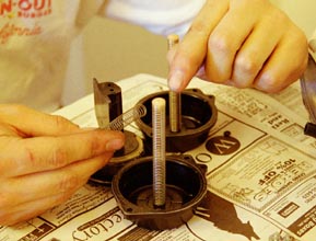
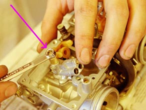
can be tricky.
Factory Pro sells a
tool, but I used the
following three
methods to triple
check my work. First
I aligned the top of
the float with the
point on this caliper
and measured that.
Then I used a ruler
and sighted across
the top.
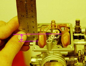
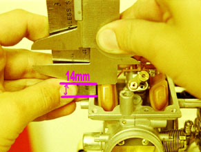
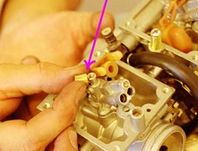
conjunction with something flat across the top of the float,
such as this caliper. Whatever the method, I went with the
recommended 14mm.
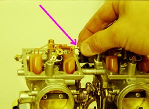
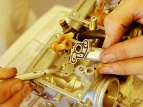
pin to let the float come off.
raise or lower the height. It's really hard to explain how to do this
and how much to do it, but you will see once it's apart.
put the covers on. Use the new screws because the
old ones are junk. Make sure the floats raise and
lower without the metering dealers binding up and
make sure they are still springy.
the horn up into the space inside the frame.
to the other side for it to fit, but it was easy
after I loosened the top nut.
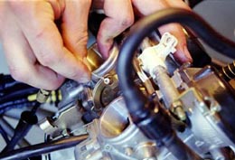
Everything should go on like it came off, there are no surprises. Once on,
check that the throttle cables operate smoothly and the blades open fully.
Adjusting the mounts on the carbs shouldn't be necessary, all the fine
adjusting should be done at the handle. You want a slight amount of slack at
the grip, forward and backward, and the blades should open fully. If not, use
the adjuster screw to loosen or slacken the cable (top or bottom) until it is
right. Follow the procedure in my throttle cable adjustment article.
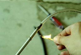
wanted all the hoses to merge into one (the two float drain tubes and
this drain tube). But, they are different sizes.
screwdriver to stretch it. Then it slid
on easily.
reconnected the fuel hose, routed the breather hoses for the carbs off to the side, tightened the runner-to-carb hose
clamps, mounted the air cleaners, attached the choke cable, and double checked all the bolts. Once finsihed, it doesn't
seem so hard, but the real problems were the float height and the battery box, which is why I went with such a high
difficutly level. Not that it's hard to understand, just that it's a pain if you know what I mean. After I fired it up, I let it
warm up then synchronized the carbs. That's all it took to get it running. I am still in the info-gathering stage before I
do any more tuning. Stay tuned!
Check out www.factorypro.com for
tuning tips and info on their jet kits.
are those of myself and do not reflect those of Ducati or its affiliates. The "DUCATI" logo and "Circle D" are registered trademarks of Ducati Motor Holding,
S.p.A., all other content on this website is copyright 200, Monster Man Productions.